An Overview:
I learned about the design of Fire Protection (FP) Systems based on national and state safety codes, including NFPA 14. I applied this knowledge to several ongoing projects around the Boston area. I constructed industry standard field drawings, head cut back drawings, record drawings, and material stock lists using Revit and Hydra CAD/LIST to insure accurate and efficient pipe installation. Additionally, I collaborated with a senior-level engineer to conduct a field survey to determine the location of an existing FP system and accurately construct a dimensioned layout in Revit.
PROJECTS

MXD Residential Tower
Cambridge, MA
Set to become the tallest building in Cambridge at over 37 stories!
Work Samples:
The work samples shown below are from miscellaneous projects and practice drawings. They have been approved by my supervisor to insure no confidential information is shared.
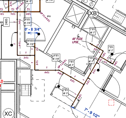
Field Drawings:
-
The purpose of a field drawing (FD) is to take a finalized FP system layout and label it with dimensions, pipe tags, elevation tags, and key feature callouts. The FD is then sent to the site with the fabricated material to insure accurate and efficient installation.
-
An FD should be kept organized and easy to read. It should be detailed enough so that the field installation runs smoothly, but not too much to become cluttered.

Dimensions

Pipe Tags

Key Feature Callouts

Elevation Tags

Flex Pipe Tags
-
Dimensions: For FDs, dimensions are taken from structural elements such as a concrete core wall, steel beams, and columns. Typically, when pipe is being installed, the walls have not been erected.
-
Pipe Tags: Every pipe has a label/name to ensure that each piece of pipe gets installed in the intended location. Most pipe is fabricated off-site and transported in bundles to the site. Each pipe also has a labeled diameter and length (ft and/or in).
-
Elevation Tags: These tags are given to insure the pipe is installed at the correct height. Two numbers are given. The first is the below top of steel (BTS) dimension. If the steel beams are exposed, this is the preferred dimension as it is typically less than 1 foot and thus, is easy to measure. The second is the above face of floor (AFF) dimension. This dimension is given from the floor's face or, in the case of an uneven or sloping floor, from a predetermined benchmark level.
-
Key Feature Callouts: Some areas of pipe may be complex and therefore, hard to visualize on a floor plan layout. These features are called out. Examples include sloped pipes or pipe fittings connected directly together.
-
Flex Pipe Tags: Flex pipes are used to add flexibility to the final location of the sprinkler head. This is key especially in tiled ceilings where symmetry is desired. These tags give the length of the flex pipe and sometimes a low profile short elbow (LPSE) tag (generally used in small/narrow areas.

BEFORE

BEFORE

AFTER

AFTER
Head Cut Back Drawings:
-
The purpose of a head cut back drawing (HCB) is to accurately dimension a sprinkler head location.
-
Typically, sprinkler heads are not installed with the pipe because the ceilings and walls are not finished.
-
It is important to give at least 2 perpendicular dimensions for each head to insure proper installation in the x-y plane.
-
Side wall sprinklers are also given elevation tags. These dimensions are typically taken from the bottom of the finished ceiling. Each head has a safety range of elevations to insure proper coverage of the a given space.

BEFORE

VS
HCB

FD
Stock Lists:
-
Stock lists of pipes and fittings are compiled so that the fabrication shop can construct and send to a site the correct material.
-
Simply put, each pipe gets a name such as A1 or 306.1.
-
The processes for stock listing steel and CPVC pipe are slightly different as shown in the table below.

-
Along with the stock list, a “loose material” list is compiled to document the types and the quantity of pipe fittings and accessories needed. This is generally done by hand.
STEEL
CPVC

FD

HydraLIST
FD
HydraLIST


Pipe Labels and Instructions for FAB Shop
Field Survey:
-
The purpose of the field survey is to determine the layout of a space accurately.
-
This includes highlighting key architectural features and occasionally features of other trades, such as plumbing, electrical, and HVAC.
-
It also requires dimensioning any existing FP system. This includes XY dimensions and vertical elevations.
-
It is often drawn out by hand on paper first and then input into Revit as a CAD file. (Sometimes measurements are directly input into AutoCAD or Revit.